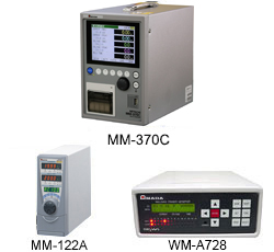
Weld checker (desk-top type): MM-370C.MM-122A.WM-A728
- Home
- Products
- Fine Spot Welders
- Weld Head/Checker and Tester
- Weld Head
- MM-370C.MM-122A.WM-A728
[ MM-370C ]
Possible to measure current, voltage, welding time, weld force, and displacement value.
- ◆USB memory device connectable
Measured data and waveform data can be saved in a USB memory device. - ◆Bidirectional communication
Connected MM-370C with a PC, data can be both write and read. - ◆Polarity selectable
Displacement value can be read in both + (plus) indication and – (minus) indication.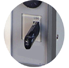
- ◆Supports various types of welders.
Supports single-phase AC welders, DC inverter welders, AC inverter welders, and transistor type welders.
- ◆Simple operation with a dial
Turn the dial to scroll the screen, move the cursor, and select items. Press the dial to select the item where the cursor is located.
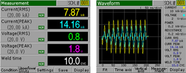
- ◆Clear display of the current and voltage
320x240 dots/4.7-inch color LCD screen.
- ◆Various display capability
Displays various welding waveforms without using an oscilloscope.
- ◆Waveform re-display feature (FIT feature)
The displayed waveform can be shifted and zoomed in and out in the screen. Even if the waveform of where you would like to observe went off the screen, it can be back to display the waveform again. (Pat. Pend)
- ◆Supports multiple languages
You can select the language from Japanese, English, Chinese, Korean, German, French, and Spanish.
- ◆Recording and transferring of data
- The measured values and waveforms can be saved in a memory or transferred out to PC for analysis.
- Data transfer can be done in the RS-232C to PC.
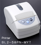
- Data can be printed out by the local printer equipped with the device.
- ◆Options◆Display screen
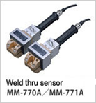
- The applied force and weld current can be measured simultaneously while welding (Optional weld thru sensor, MA-770A or MA-771A is necessary).
- Voltage signal (Max.±10V) from other sensor can also be measured due to the external input facility.
-
- ◆Accessories

[ MM-122A ]
Highly functional and highly precise weld monitor (checker) for various weld current waveforms.
- ◆Cyclical and accurate display of the welding time for AC inverter welding.
- ◆Light and compact body. Fast measuring speed, and easy installation.
- ◆Simple "turn" and "press" operations with a single button.
- ◆The measuring unit from "ms" or "Cycle" on measuring welding time can be selected.
- ◆Communication facility is equipped on standard.
Measured values can be transferred to a PC and the evaluation criteria can be changed from the PC. RS232C and RS-485 are equipped on standard
[ WM-A728 (Weld checker dedicated to PULSETIG welding) ]
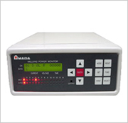
- ◆The input/output signal LED indicators on the front panel allows you to grasp input signals to the monitor at a glance.
- ◆Number of setting conditions: 32 at the maximum (Equipped with a function of copying the setting values to other channels)
- ◆Simultaneous display of the current and time
- ◆Enhanced tolerance for noises due to arcs
- ◆Compatible with mold-type toroidal coils
- ◆Measurement range setting feature: Performs arithmetic operations and displays the current values in a specified range (Ready for current measurement excluding up and down slopes)
- ◆AC power supply ready for world-wide use
- ◆Selectable pulse output time for output signals (TACT, 50ms, 100ms, and 300ms)
[ MM-370C ]
| Model | MM-370C | ||
|---|---|---|---|
| Current | Measuring range | (1)0.1 - 2.000kA (2)0.3 - 6.00kA (3)1 - 20.00kA (4)3 - 60.0kA (5)10 - 200.0kA |
|
| Measured value | Arithmetic mean RMS or PEAK | ||
| Measurement accuracy | For range (1)(3)(5) ± (1%rdg+9 - 20dgt) For range (2)(4) ± (1%rdg+3 - 7dgt) *1 |
||
| Voltage | Measuring range | 2 ranges, 6.00 V or 20.00 V | |
| Measured value | Arithmetic mean RMS or PEAK | ||
| Measurement accuracy | ±(1%rdg+3dgt) | ||
| Welding time | Measuring range | AC mode | DC mode |
| 50Hz:0.5 - 500.0CYC/ 60Hz:0.5 - 600.0CYC |
1 - 2000ms | ||
| Force | Measuring range | 4.90 - 98.06N(MA-520), 49.0 - 980.6N(MA-521), 490 - 9806N(MA-522) |
|
| 245 - 4903N(MA-770A), 490 - 9806N(MA-771A) | |||
| Measured value | RMS or PEAK | ||
| Measurement accuracy | ± (Load cells full scale error +2%rdg+29dgt) | ||
| Displacement (option) | Measuring range | ±30.000 (When sensor with resolution of 1µm or finer is used) |
|
| ±300.00 (When sensor with resolution of 10µm or finer is used) |
|||
| Measured value | Displacement at end of delay time, start measuring from welding start | ||
| Measurement accuracy | ±0.05% of full scale | ||
| Conduction angle measurement | 0 - 180 degree (CYC mode only) | ||
| Number of schedules | 127 schedules | ||
| Printer | Printable items: Measurement data, waveforms, all cycles, setting condition data, screen copies, print history | ||
| Input power supply voltage | Single-phase 100 - 240VAC ±10% 50/60Hz | ||
| Power consumption | 50W | ||
| Mass | Approx. 5kg | ||
- *Specifications subject to change without notice.
[ MM-122A ]
| Model | MM-122A | ||||||
|---|---|---|---|---|---|---|---|
| Measurement | Current | Measuring range | 0.010 - 0.199kA (Only when 10x sensitivity coil used) 0.100 - 1.999kA 1.00 - 19.99kA 10.0 - 199.9kA | ||||
| Measured value | The peak value of the total welding or arithmetic mean RMS in the measured range can be measured. | ||||||
| Display | 4-digit digital display (7-segment LED) |
||||||
| Measuring range setting | Start | AC | 000-500 cycles (31 conditions) | DC | 0000 - 2000ms (31 conditions) | ||
| End | (Supports 50- 250 Hz) | 0.50 - 25.00ms(31 condition) | |||||
| Measurement accuracy | RMS ± (2%rdg + 4dgt) *1, PEAK ± (2%rdg + 10dgt) |
||||||
| Detection method | Toroidal coil | ||||||
| Time | Welding-cycle / Pulsewidth | Measuring range | The maximum measurement duration is 2 seconds. Single-phase AC 0.5-100 cycles (50 Hz)/0.5-120 cycles (60 Hz) | ||||
| AC inverter type 0.5 - 500 max. cycle (depending on welding current frequency) or 0.50 - 2000ms (until half time of IP for TH) | |||||||
| Display | 4-digit digital display (7-segment LED) | ||||||
| Detection method | Toroidal coil | ||||||
| Conduction angle | Measuring range | 30 - 180° Maximum conduction angle within welding time | |||||
| Measurement accuracy | ±5% of full scale | ||||||
| Detection method | Toroidal coil | ||||||
| Voltage | Measuring range | - | |||||
| Measured value | - | ||||||
| Display | - | ||||||
| Display | - | ||||||
| Measurement accuracy | - | ||||||
| Detection method | - | ||||||
| Current & voltage measurement value | RMS | Cycle display: Arithmetic mean RMS for each half cycle. "msec" display: Arithmetic mean RMS per each 1msec | |||||
| Transistor type: RMS from the start to the end. Capacitor type: RMS from the start of welding to the TH. | |||||||
| PEAK | Maximum PEAK during entire welding time | ||||||
| Pressurization | Measuring range | - | |||||
| Detection method | - | ||||||
| Monitoring | Welding current | Upper/lower limit 31 schedule setting. Setting range 0 to Maximum measurement range | |||||
| Welding time | Upper/lower limit 31 schedule setting. Setting range 0 to Maximum measurement range | ||||||
| Status alarm display | Each dedicated lamp for upper limit, lower limit and "in-rage" will show the status. | ||||||
| Status alarm signal | "GOOD", "NG-H", and "NG-L" semiconductor relay | ||||||
| Impulse setting | 0 - 9 (Sets the location for measuring pulsation welding.) | ||||||
| Counter | 99999 max. 5 digits | ||||||
| Printer | Option (BL2-58PN-MYT) | ||||||
| Print-out the following; the current welding time, evaluation result, schedule no., conduction angle and *ACS data counter value been measured and displayed. *All Cycle Schedule |
|||||||
| Step up | 11 - 9 steps | ||||||
| Communications output | RS-232C/RS-485 The current, weld-time, evaluation results counter value and schedule data measured and display can be transfer in the communication facility. |
||||||
| Power requirements | Single-phase 100 - 240VAC ±10% (50/60Hz) or 24VDC ±10% | ||||||
| Mass | 1.9kg | ||||||
| Operating ambient temperature | 0 - 40°C | ||||||
| Power consumption | 112W max. | ||||||
- *1: rdg: Read value (2% of displayed measured value) dgt: One count of digital display (3dgt ; There is an error of 3 counts in the final digit.)
- *2: Projections not included
* Specifications subject to change without notice.
[ WM-A728 ]
| Model | WM-A728 | ||||
|---|---|---|---|---|---|
| Toroidal coil | TC-M101 | ||||
| Measuring current | Range | 100A: 0.1A - 99.9A 200A: 1A - 199A 300A: 1A - 499A |
|||
| Value | RMS | ||||
| Accuracy | +/- 2% / FS (including troidal coil and monitor) | ||||
| Measuring time | Range | 0.1ms to 4.99sec | |||
| Measuring voltage | Range | - | |||
| Value | - | ||||
| Accuracy | - | ||||
| Detecting method | Dedicated toroidal coil | ||||
| Number of measuring schedule | 32 | ||||
| Power requirements | 85 to 250VAC, 50/60Hz Auto-switch, 2A max. | ||||
| Memory | EEPROM memory | ||||
| Ambient temperature | 0 to 40°C (No condensation) | ||||
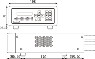
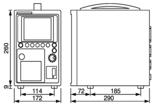
- ◆MM-370C
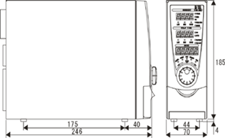
- ◆MM-122A
- ◆WM-A728
